My PhD is based in Longyearbyen, Svalbard, where I look at the shale-dominated caprock overlying the reservoir targeted by the Longyearbyen CO2 Lab. The Longyearbyen CO2 Lab is a pilot carbon capture and sequestration (CCS) project that provides key input to CCS activity elsewhere, including to the Norwegian CCS Research Centre (NCCS) that supports my PhD.
Fieldwork is a rather large component of the work, and – like my supervisors before me - I have spent many, many months in the outdoors these past four years. Working in a challenging environment such as Svalbard teaches you to appreciate flexibility, here often referred to as polar flexibility (aka – off the charts flexibility), as things rarely, if ever, go according to plan.
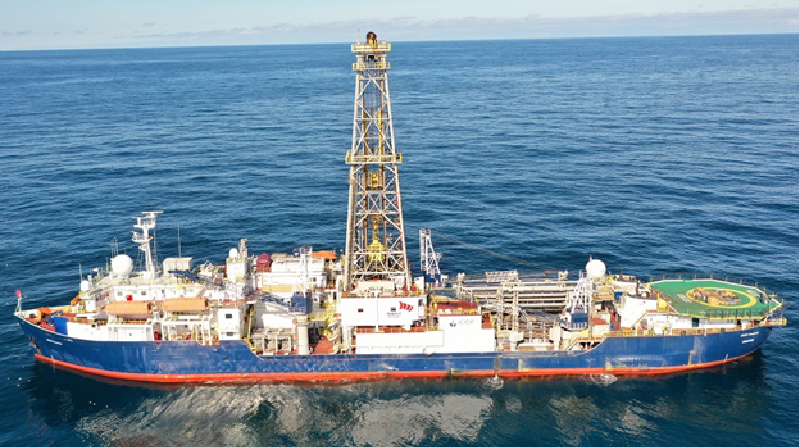
I joined International Ocean Discovery Program Expedition 396 to study the carbon sequestration potential of basalts off the shore of Norway, a very different but exciting setting. I previously described my experiences as onboard scientists in DEEP’s travel blog and on the NCCS SINTEF blog. In the latter I also alluded to my follow-up work: the rock physics testing of selected basalt mini-core samples at the Norwegian Geotechnical Institute (NGI) Rock Physics Laboratory.
Having spent several months in the lab, it turns out that experimental lab work is very similar to the challenges encountered in the field in Svalbard. Are there polar bears that cause a “mission abort”? No, luckily not. Are there unexpected challenges and setbacks? Absolutely - more so than I had imagined possible at the start. Most challenges are due to the unique setup of the experiment: not only can we regulate pressure and change the fluids within the sample, but the entire setup is mounted within a CT scanner that allows us to image the sample under stress as well as capture the flow of fluids through it.

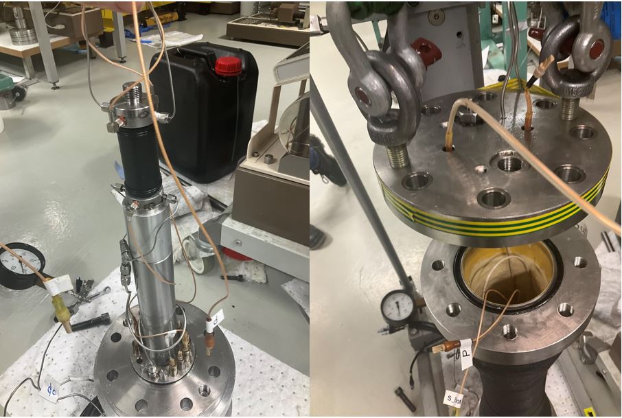
The rock physics experiments involved placing the sample in a protective sleeve, with the top and base connected to fluid flow tubes and data sensors. The fluid flow tubes enable fluid substitution, i.e. flushing fluids (brine, CO2) through the porous basaltic samples. The data sensors capture seismic wave velocities and resistance, key rock physics parameters used in subsurface imaging. To apply stress on the sample, the setup was put within a pressure cell, which was then filled up with incompressible hydraulic oil. Incompressible means that volume or density does not change with pressure.
The addition or removal of small volumes of oil then changes the pressure rather drastically, which enables the measurement of rock physics parameters at different pressure or stress levels. The pressurized oil surrounding the sample also poses a risk. A leak in the tubing, the protective sleeve or even the cell itself quickly spells the end of an experiment; Yes, there were a few dummies/trials involved before we got things right…

Geophysics and the Earth’s geophysical responses tell us about what is happening in the subsurface. For instance, solid rocks (without pore space) typically feature higher seismic wave velocities; completely dry rocks are much more resistive to electrical currents than brine-saturated rocks; and high pressures and stresses affect the responses in different ways. As we cycle through pressure regimes and change pore fluids, we learn about the geophysical responses for all these different combinations within a single experiment – a huge payoff for the significant risk of experimental setup.
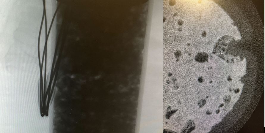
The CT scans are crucial to image how far the pore fluids have reached into the pore space at a given moment in time. The scans thus link rock physics measurements and geophysical responses to e.g. the degree of saturation, pore fluid type, stress and permeability; all important parameters where reservoirs and concerned.
The predictive relations obtained between the geophysical responses and physical properties (e.g. saturation, the effects of different pore fluids, stress levels, porosity, permeability) facilitate the assessment of the subsurface beyond the immediate vicinity of the boreholes drilled during IODP Expedition 396. The relations will also aid the carbon sequestration appraisal of reservoir and caprock properties on the scale that is needed to assess the basalts of the Norwegian Mid-Continental Margin.
That is, however, still a long way ahead. For now, we are mostly excited that we succeeded in measuring geophysical responses at a range of pressures and pore fluids; that we managed to measure permeabilities at several stress regimes; and that we have managed to inject CO2 into the brine-saturated sample to image how CO2 flows through the subsurface at the pore-space scale, documented by CT scanning.
There are thousands of velocity and resistivity measurements and a TB of data to go through; almost a hundred CT scans to compare, analyse and integrate, and half a dozen permeability measurements to appraise. Hopefully, once all is done, the integrated work provides a first rock physics template tuned to the basalts of the Norwegian Mid-Continental Margin.
This would not have been possible without all the great support I have gotten from the DEEP research school, NGI, NCCS & partners, Volcanic Basin Energy Research AS, the Petroleum Research School of Norway, and the Meltzer Research Fund 2022 during both the expedition itself and the follow-up research stays in Oslo.