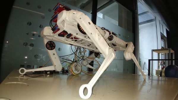
There are many different ways to explore this:
- testing different control algorithms using the same physical hardware.
- Both previously described algorithms, and possibly new/modified versions..
- Does it make sense to switch between different algorithms depending on speed and torque requirements, or is one always better? (eg space-vector modulation vs sinusoidal pulse-width-modulation) ?
- Both previously described algorithms, and possibly new/modified versions..
- Determine what sensors we should use in legged robots:
- To what degree do we need digitalization of current running in a motor if we can create a model for the motor?
- How can we create a best possible model?
- How much and what type of data do we need to build a model
- Can we run a legged robot using position sensors (quadrature) alone, or do we need AD-conversions running on all three phases.
- How can we create a best possible model?
- To what degree do we need digitalization of current running in a motor if we can create a model for the motor?
- Evaluate computational delays by creating a system that allows computation to be done at the lowest possible level.
- What type of data should flow between different modules in a motor control system used for robotics?
- Is there a preferred architecture for motor control?
As a master project you may work with one (or more) of these problems or tasks.
We are open to suggestions if you have an idea that might fit, or we can help you find one or more relevant problems to explore, depending on your interests.
Here is one concrete example that may be used as a master project:
Example: Motor driver algorithm development and comparison
Thesis goal:
To create an FPGA based motor control system and a test rig to compare various algorithms using different motors and loads. The system shall be used to classify various motor parameters to enable motor control that that adapts to the motor in use.
Methods
By either testing one motor against another, measuring force/torque by utilizing a load with a specific rotational inertia, create mapping in ROM or neural networks that can be used for control purposes:
- Recognize a particular motor / type
- To find if the power output is consistent (errors) throughout full circular movement.
- To see if a motor is suitable for a certain task
- To recognize wear and drop in performance
- Control the power/torque output at different angles and speeds
- In meaningful physical sizes (ie. with known moment of inertia of a test target we should be able to map the physical response of a system using SI units).
The system should consist of motor with position controller and current feedback loops (preferably for each phase)
The results can be used to
- Compare different methods
- Find which methods gives best results
- At low or no speed
- At higher angular velocities
- When varying speed
- Define what granularity makes sense using different types of motors
- Ie how much testing does it make sense to do before results have diminishing values (non measurable).
Hardware
Zynq platform (TRENZ), TI DRV8305 or a similar driver board, Brushless DC motor, Position sensors, etc.
Articles
A Survey of FPGA-Based Robotic Computing (2021)
Robotic Controller: ASIC versus FPGA—A Review (2018)
Position and Speed Control of Brushless DC Motors Using Sensorless Techniques and Application Trends (2010)
Cogging Torque Reduction in Brushless Motors by a Nonlinear Control Technique (2019)
